This past year, I was the Engine Analysis team lead at Liquid Rocketry at Illinois, a liquid rocketry club focusing on pump-fed rocket engines. The tasks assigned to this role encompass both thermal and structural analysis of current and past rocket engines primarily through the development of python scripts. Retaining ring enclosures, nozzle thickness calculations, and 1D-flow heat transfer analysis are all tasks that I've written code for. Additionally, I was also a part of our Special Research and Development (SRD) team, where I developed a complex heat flux script for usage in coolant calculations on a regeratively cooled engine.
Heat Transfer Code
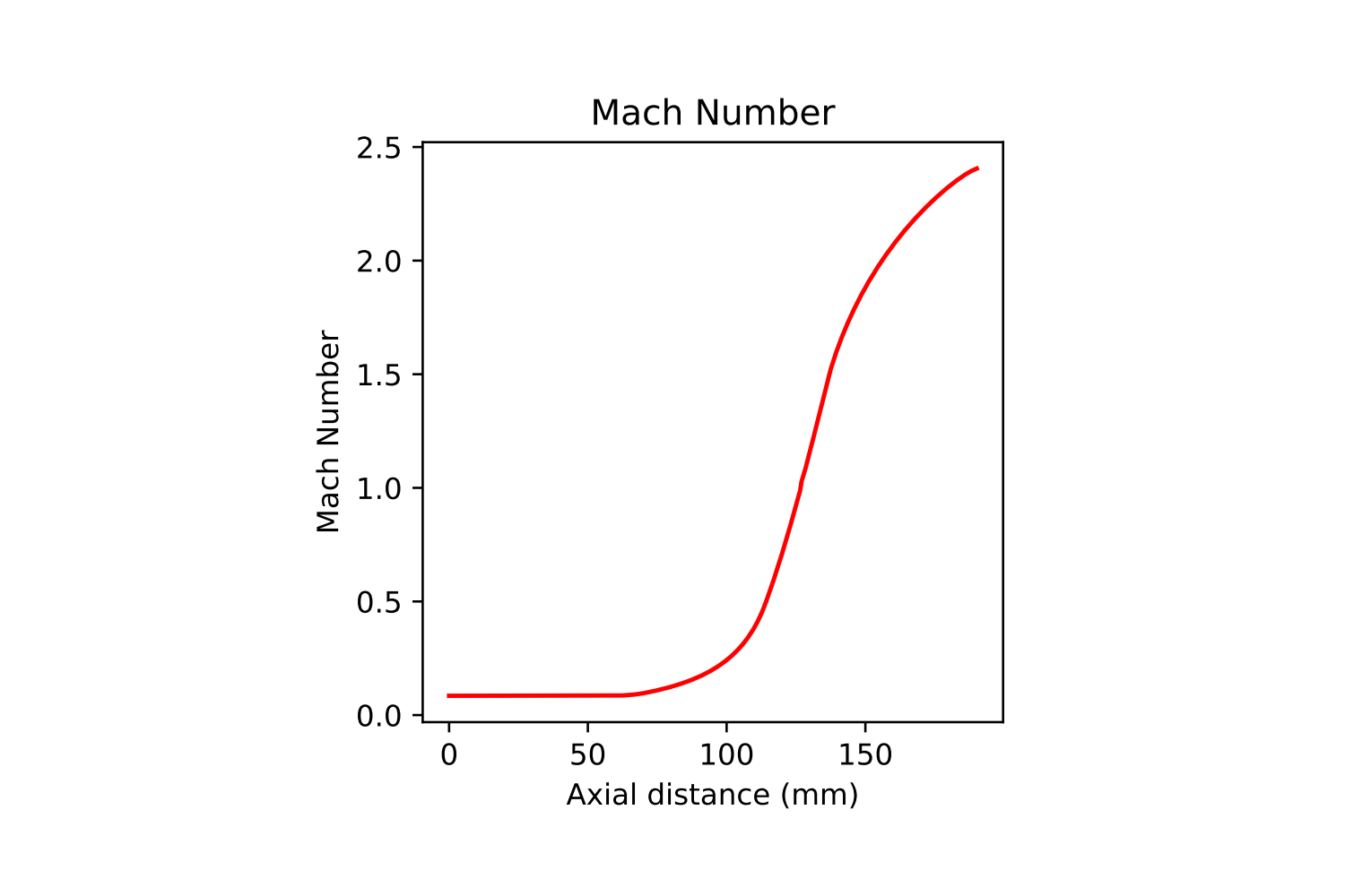
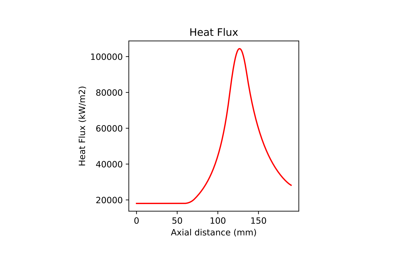
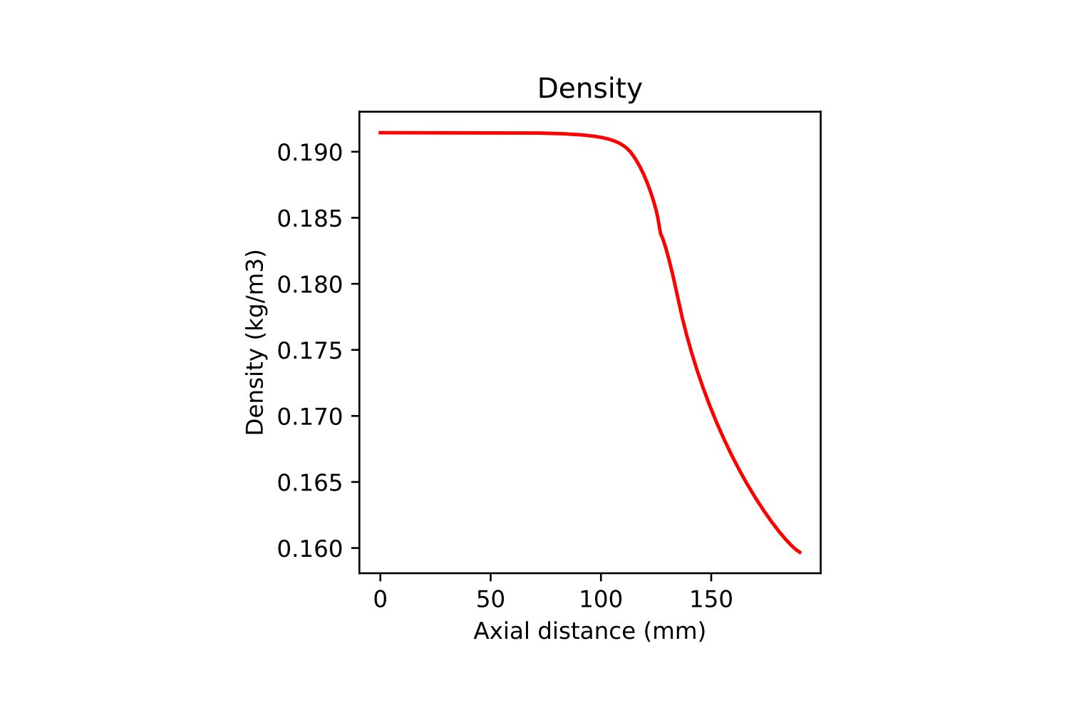
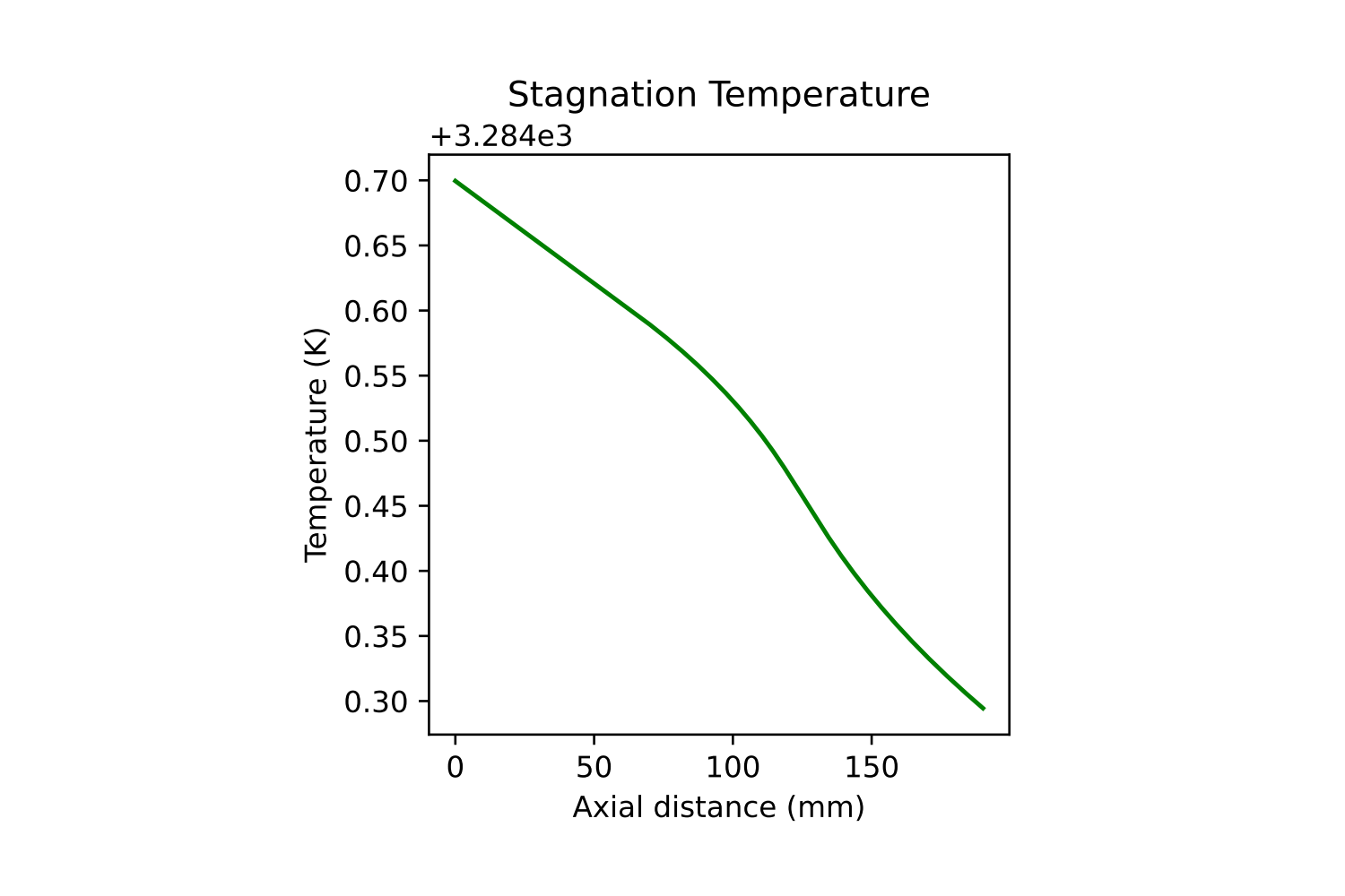
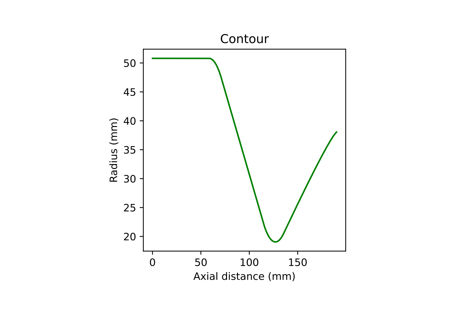
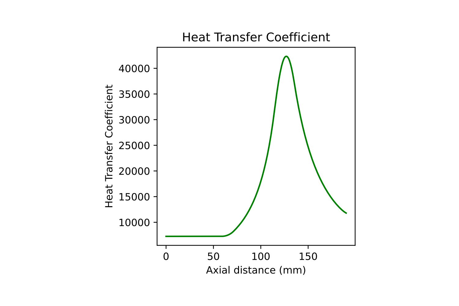
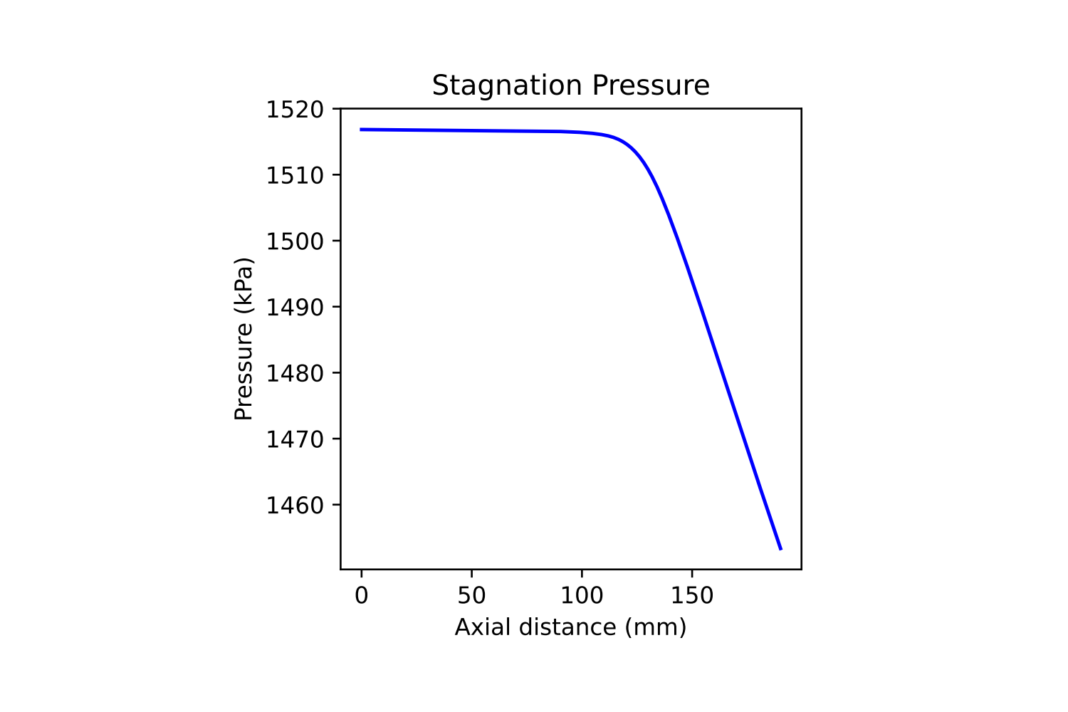
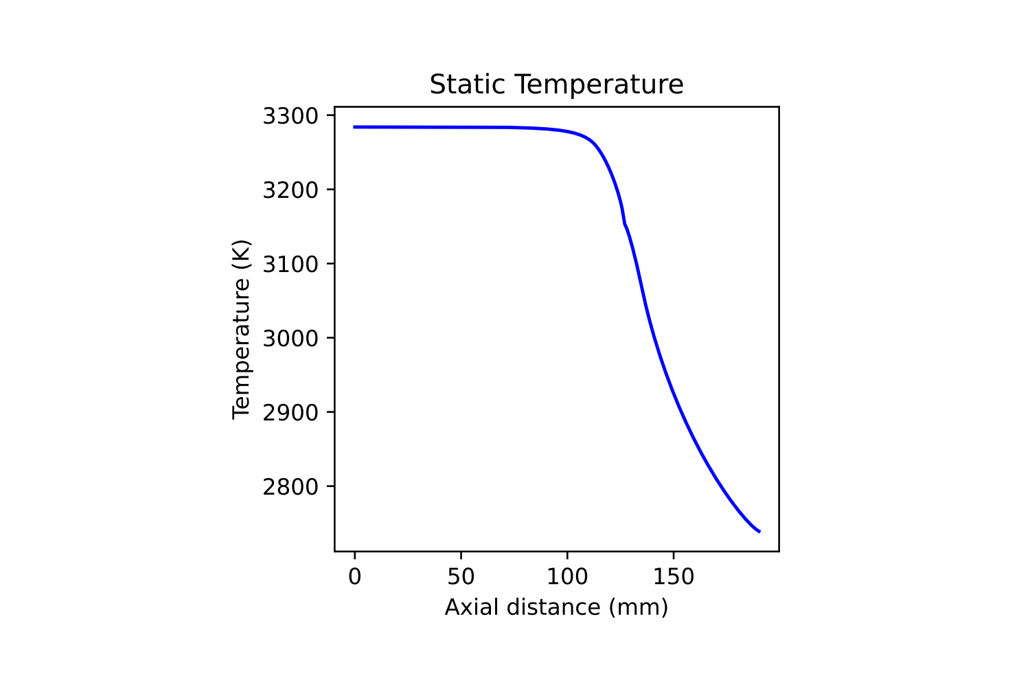
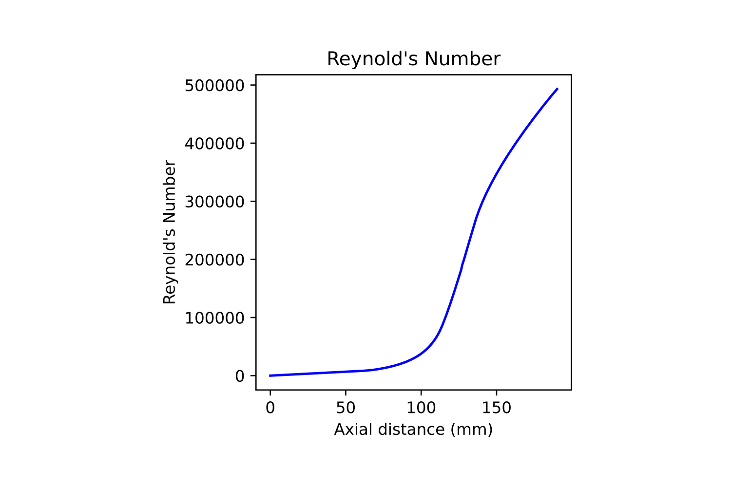
Creating this heat transfer script was one of the most challenging engineering tasks I've ever faced. I came into this role knowing nearly nothing about compressible fluid dynamics or heat transfer, but quickly learned the roped by reading various textbooks and papers. This model is based off the general form of quasi-1-dimensional flow analysis with heat transfer and friction found in Greitzer 2004 and uses the influence coefficient matrix to iteratively converge on a solution along the length of the engine chamber and nozzle contour. To simplify the calculations, we assumed constant cp along the entire contour and also assumed that our combustion gases are fully reacted into products immediately at the injector face. No heat transfer due to combustion was taken into account, and the mole fractions of the gases are simply the fully reacted products. Using these assumptions, we can see on the right the results of a sample contour using LOx and IPA at an OF ratio of 1. For this specific test we assumed a constant initial wall temperature of 800K, a chamber temperature of 3300K, and an initial chamber pressure of 220psi. Using these initial parameters we were able to calculate the instantaneous heat flux from the gas to the wall along the chamber and nozzle with heat transfer and friction effects included.
Bearing Area Code
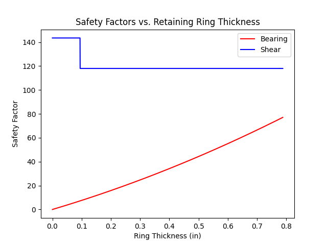
As part of my role as the Engine Analysis lead, it's my job to ensure that the proposed graphite nozzle contour designs will not fail or cause any other component to fail. This includes both bearing and shear failure analysis of the nozzle contours and designing retaining rings that will provide a high factor of safety against both of these failure modes. This code intakes a nozzle and chamber contour and outputs a graph of the retaining ring thickness against both bearing and shear safety factor. Note that the likelihood of failure in shear is extremely low causing the safety factor to be in the hundreds. The code also intakes the size and location of O-ring sealing grooves to aid in the shear calculations, as well as the bearing strength and shear strength of the nozzle material. The example on the right shows results for the same contour as the heat flux calculations above with a 1/16 in thick O-ring groove located 2.5 in from the edge of the nozzle.